This project provides libraries and examples for the Ada programming language on the RP2040 microcontroller and the Raspberry Pi Pico development board.
Code snippets included here are meant to be illustrative but cannot be compiled standalone. For working examples, see pico_examples.
This document assumes you are familiar with the Ada language. If you are new to Ada, learn.adacore.com has an excellent introduction.
Getting Started
Install Alire
The Alire package manager is used to manage dependencies and build software using these libraries. You will need to download and install Alire before continuing.
Assuming you are running Linux on x86_64, the following commands should work.
curl -L -O https://github.com/alire-project/alire/releases/download/v2.1.0/alr-2.1.0-bin-x86_64-linux.zip
unzip alr-2.1.0-bin-x86_64-linux.zip
sudo cp bin/alr /usr/local/bin
Create a new project
Use Alire to create a skeleton project and add a dependency on pico_bsp.
alr init --bin hello_pico
cd hello_pico
alr with pico_bsp
If Alire prompts you to install tools like unzip and git, accept these changes. If prompted to select a toolchain, choose the most recent versions of gnat_arm_elf and gprbuild.
Next, edit hello_pico.gpr to import pico_bsp and add the Target, Runtime, and Linker configuration near the top.
with "config/hello_pico_config.gpr";
with "pico_bsp.gpr";
project Hello_Pico is
    for Target use "arm-eabi";
    for Runtime ("Ada") use "light-cortex-m0p";
    package Linker is
        for Switches ("Ada") use Pico_BSP.Linker_Switches;
    end Linker;

    for Source_Dirs use ("src/", "config/");
Build the project.
alr build --developmentIf the build was successful, there will be an ELF binary in ./bin/hello_pico.
Flashing the Pico
There are several ways to get your compiled code onto the Pico. It is highly recommended that you setup a Serial Wire Debug (SWD) debugger so that you can run GDB. The linked video shows how to setup a Raspberry Pi Zero as a SWD debugger, but other debug adapters like the Segger J-Link should work.
Using GDB, you can load the ELF binary and run it. If you are not using an OpenOCD based debugger, these commands may be slightly different. Consult your debugger’s documentation if this doesn’t work.
eval $(alr printenv)
arm-eabi-gdb bin/hello_pico
target extended-remote localhost:3333
monitor arm semihosting enable
load
run
If you cannot use SWD, pico-debug can be loaded into memory on the Pico to allow you to debug over USB. If you use pico-debug, your code cannot make use of the USB port or the second CPU core and pico-debug will use up some memory. See the pico-debug README for more information.
picotool can convert a compiled ELF binary to UF2 format, which can be loaded onto the Pico over USB after holding the BOOTSEL button. If you choose this option, you will not be able to debug your code when it crashes.
picotool uf2 convert bin/hello_pico -t elf bin/hello_pico.uf2
sudo picotool load bin/hello_pico.uf2
Blinking an LED
You’ve probably noticed that we haven’t written any code yet! Let’s change that with the traditional blinking LED demo.
Edit src/hello_pico.adb
with RP.Device;
with RP.Clock;
with RP.GPIO;
with Pico;

procedure Hello_Pico is
begin
   RP.Clock.Initialize (Pico.XOSC_Frequency);
   RP.Device.Timer.Enable;
   Pico.LED.Configure (RP.GPIO.Output);

   loop
      Pico.LED.Toggle;
      RP.Device.Timer.Delay_Milliseconds (250);
   end loop;
end Hello_Pico;
At boot, the RP2040 is configured to use it’s internal oscillator to run the CPU’s clock. This oscillator is both slow and inaccurate, so an external 12 MHz crystal oscillator is included on the Pico board. The RP.Clock.Initialize procedure reconfigures the CPU to run at 125 MHz using the external crystal as a reference. This is needed for accurate timing and will almost always be the first call your program makes.
The internal Timer peripheral counts up at 1 MHz and can be used to implement delays. RP.Device.Timer.Enable configures an interrupt needed for Delay_Milliseconds.
By default, all of the GPIO pins are inputs, so we configure the pin named Pico.LED as an output.
The loop toggles the LED on and off every 250 milliseconds. Use alr build to recompile the project and load it using your debugger. If all goes well, the onboard LED will blink!
Development Guide
Source repositories
-
rp2040_hal contains drivers and register definitions for the RP2040’s onboard peripherals.
-
pico_bsp provides pin definitions and drivers for the Raspberry Pi Pico development board and compatible addons.
-
pico_examples demonstrates the functionality of rp2040_hal and pico_bsp and serves as a template for new projects.
Versioning
Releases are tagged and added to the Alire index regularly. We follow the Semver pattern, so the API provided by these drivers can be considered stable unless the major version number changes.
This documentation relates to the master branch of the source repositories and may differ from what’s available in Alire. If you need to use unreleased features or fixes, you can pin your project to the master branch. The master branch is unstable and may break your code, so this is not recommended unless you have a good reason.
alr pin --use=https://github.com/JeremyGrosser/rp2040_hal rp2040_hal
Hardware overview
The Raspberry Pi RP2040 is an ARM Cortex-M0+ microcontroller. Detailed specifications and low level documentation can be found in the RP2040 datasheet.
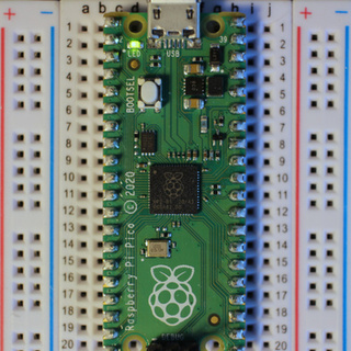
Pico pinout

The Raspberry Pi Pico is a low cost development board that includes the RP2040, a micro USB port, crystal oscillator, voltage regulator, and a green LED. The Pico datasheet includes schematics, pinout diagrams, and design recommendations.
If you wish to develop a custom board using the RP2040, the hardware design guide contains reference designs and layout tips.
Clock configuration
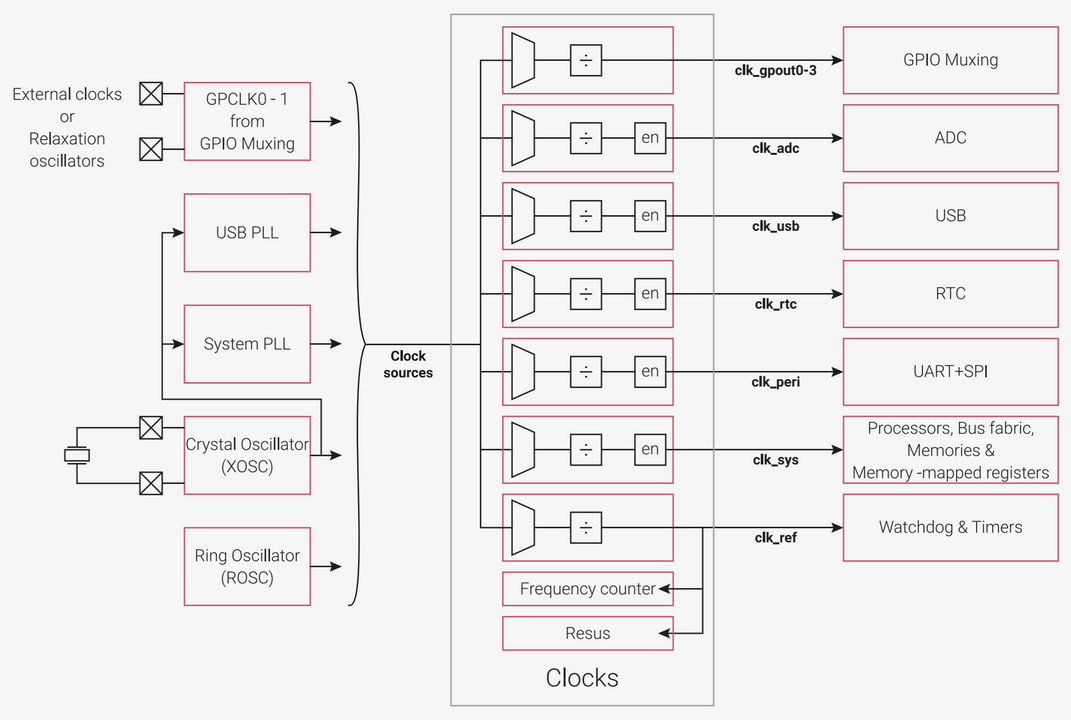
See section 2.15 of the RP2040 datasheet for a detailed description of the clock hierarchy.
Name |
Frequency |
Enabled |
clk_sys |
125 MHz |
Yes |
clk_peri |
125 MHz |
No |
clk_ref |
1 MHz |
Yes |
clk_rtc |
46.875 KHz |
No |
clk_usb |
48 MHz |
No |
clk_adc |
48 MHz |
No |
clk_gpout0-3 |
Not configured |
No |
Some peripherals, such as the UART, need a clock enabled before they can be used.
RP.Clock.Enable (RP.Clock.PERI);Clocks may be disabled to reduce power consumption.
RP.Clock.Disable (RP.Clock.PERI);
The RP.Clock.Frequency function uses the internal frequency counter to measure internal clocks. This is used to configure dividers and enforce minimum operating frequencies in preconditions. Most drivers provide convenience wrappers that perform these calculations for you.
declare
    Target_Frequency : constant Hertz := 1_000_000;
    Divider          : constant Positive := Positive (RP.Clock.Frequency (RP.Clock.SYS) / Target_Frequency);
begin
    Put_Line (Divider'Image);
end;
GPIO
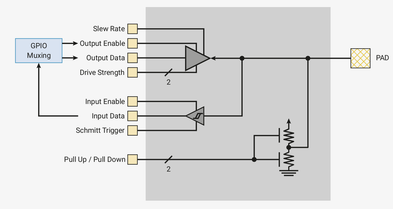
type GPIO_Pin is range 0 .. 29;
type GPIO_Point is new HAL.GPIO.GPIO_Point with record
    Pin : GPIO_Pin;
end record;
Naming pins
BSP packages contain names for pins that map to a schematic net name or silkscreened label familiar to the user. For example, package Pico contains the following definitions that match the board’s documentation.
   GP25 : aliased GPIO_Point := (Pin => 25);
   GP26 : aliased GPIO_Point := (Pin => 26);
   GP27 : aliased GPIO_Point := (Pin => 27);
   GP28 : aliased GPIO_Point := (Pin => 28);

   LED  : GPIO_Point renames GP25;
Basic operation
RP.GPIO.Configure has several optional parameters. The default values will configure the pin for basic Get, Set, Clear, Toggle operation.
Pico.LED.Configure (RP.GPIO.Output);
loop
    Pico.LED.Toggle;
end loop;
Pin functions
The Func parameter connects the pin to an internal peripheral, such as I2C. See 2.19.2. Function Select in the RP2040 datasheet or the Pico pin diagram for the mapping between pins and peripherals. This example also shows how Ada’s renames can be used to make it clear what a pin will be used for.
declare
    use RP.GPIO;
    SCL : GPIO_Point renames Pico.GP27;
    SDA : GPIO_Point renames Pico.GP26;
begin
    SCL.Configure
        (Mode       => Output,
         Pull       => Pull_Up,
         Func       => I2C,
         Schmitt    => True,
         Slew_Fast  => False);
    SDA.Configure
        (Mode       => Output,
         Pull       => Pull_Up,
         Func       => I2C,
         Schmitt    => True,
         Slew_Fast  => False);
end;
Interrupts
Level- and edge-triggered interrupts can be configured to call a procedure when a pin’s state changes.
declare
    use RP.GPIO;

    procedure Switch_Changed
        (Pin     : GPIO_Pin;
         Trigger : Interrupt_Triggers)
    is
    begin
        case Trigger is
            when Rising_Edge =>
                LED.Set;
            when Falling_Edge =>
                LED.Clear;
        end case;
    end Switch_Changed;
begin
    GP22.Configure (Input, Floating);
    GP22.Set_Interrupt_Handler (Switch_Changed'Unchecked_Access);
    --  Move Switch_Changed into a package to avoid the need to use Unchecked_Access here.
    GP22.Enable_Interrupt (Rising_Edge);
    GP22.Enable_Interrupt (Falling_Edge);
end;
Timing
Timer
The Timer peripheral runs at 1 MHz (1 microsecond per tick) and counts up from zero at power on. The counter is 64 bits wide and will not overflow in your lifetime. The RP.Timer package defines several procedures for getting the current timer value and delaying for a period of time. This package implements the HAL.Time interface.
Clock returns the current value of the timer, microseconds since power on.
declare
    Now : constant RP.Timer.Time := RP.Timer.Clock;
begin
    Put_Line (Now'Image);
end;
Delay_Microseconds polls Clock until a number of microseconds has elapsed. This method is recommended if you need accurate, short delays.
RP.Device.Timer.Delay_Microseconds (1_000); -- one millisecondAll of the other procedures in RP.Timer configure TIMER_IRQ_2 interrupt to fire after a time has elapsed. This allows the chip to go into a low power mode while waiting. Enable must be called before any of the interrupt driven delays may be used. Handling the timer interrupt does incur latency on the order of a few microseconds, so the actual time elapsed may be slightly longer than requested.
Use Delay_Milliseconds if you need delays longer than a few microseconds and don’t care about interrupt latency.
RP.Device.Timer.Enable;
RP.Device.Timer.Delay_Milliseconds (1_000);
A common pattern is to use Delay_Until to ensure that a loop executes on a fixed schedule. Delay_Until is the best of both approaches as it uses interrupts for low power and returns very close to the specified time.
declare
    use RP.Timer;
    T : Time := Clock; --  RP.Timer.Clock does not use interrupts, it can be called before Enable
begin
    RP.Device.Timer.Enable;

    loop
        T := T + Milliseconds (100);
        RP.Device.Timer.Delay_Until (T);

        --  Do some work here. As long as it takes less than 100ms to execute,
        --  this loop will run at precise 100ms intervals.
    end loop;
end;
Real Time Clock (RTC)
The RTC tracks the date and time in years, months, days, day of week, hours, minutes, and seconds.
The RTC is not running by default, but once initialized, will continue running as long as power is supplied. This means the time can persist through a reset. In most cases, you’ll want to check if the RTC is already running before initializing it.
if not RP.Device.RTC.Running then
    RP.Device.RTC.Configure;
end if;
RP.RTC implements the HAL.Real_Time_Clock interface. Date and time are represented by the RTC_Date and RTC_Time records.
with HAL.Real_Time_Clock; use HAL.Real_Time_Clock;
with RP.Device;

RP.Device.RTC.Set
    (Time =>
        (Hour => 12,
         Min  => 0,
         Sec  => 0),
     Date =>
        (Day_Of_Week => Friday,
         Year        => 21,
         Month       => October,
         Day         => 1));

declare
    Time : RTC_Time;
    Date : RTC_Date;
begin
    RP.Device.RTC.Get (Time, Date);
end;
The RTC_Year type has the range 0 .. 99, so you will likely need to add an offset to this value for display purposes. The rtc example includes a To_String function that converts RTC_Time and RTC_Date into an ISO 8601 string.
No support is provided for time zones, leap seconds, or daylight savings time conversion.
Pause and Resume procedures are provided to temporarily stop the RTC. Note that the Running function will return False while the RTC is paused. If the chip is reset while the RTC is paused, the RP.RTC package cannot differentiate between a paused RTC and an uninitialized one.
Serial interfaces
The UART, SPI, and I2C drivers implement the HAL.UART, HAL.SPI, and HAL.I2C interfaces to provide compatibility with other platforms. The interfaces all have Transmit and Receive procedures that provide status information to an out parameter. The RP.UART, RP.SPI, and RP.I2C_Master packages provide platform specific initialization, configuration, and status procedures that are not included in the HAL interfaces. Timeouts are implemented by polling RP.Timer.Clock.
All of the serial interfaces require clk_peri to be running.
RP.Clock.Enable (RP.Clock.PERI);GPIO pins need to be configured for the serial peripherals to interact with the outside world. See the pin diagram for information on which pins can be associated with serial functions. All serial pins should use the Output mode, regardless of the serial data direction. External pull-up resistors are recommended for buses that require them, rather than exposing the internal pull-ups to bus currents.
UART
with HAL.UART;
with RP.UART;
with RP.GPIO; use RP.GPIO;
with RP.Clock;
with RP.Device;
with Pico;

procedure UART_Example is
    UART_TX : GPIO_Point renames Pico.GP0;
    UART_RX : GPIO_Point renames Pico.GP1;
    Port    : RP.UART.UART_Port renames RP.Device.UART_0;

    Message : constant String := "Hello, Pico!";
    Data    : HAL.UART.UART_Data_8b (Message'Range)
        with Address => Message'Address;
    --  This is an implicit unchecked conversion that takes advantage of the
    --  fact that Character is always 8 bits wide.

    Status  : HAL.UART.UART_Status;
begin
    RP.Clock.Initialize (Pico.XOSC_Frequency);
    RP.Clock.Enable (RP.Clock.PERI);

    UART_TX.Configure (Output, Floating, UART);
    UART_RX.Configure (Output, Floating, UART);

    --  The default config is 115200 8n1, this example just overrides the baud rate
    Port.Configure (Config => (Baud => 9600, others => <>));

    --  A Timeout of 0 means this procedure may block forever. The default timeout is one second.
    Port.Transmit (Data, Status, Timeout => 0);
end;
SPI
SPI is a synchronous interface. For every word that is transmitted, another is received and buffered simultaneously. The SPI peripheral can buffer up to 8 words in the Transmit and Receive FIFOs. The bus clock is generated when Transmit is called. Receive should be called after every Transmit to read the same number of bytes from the FIFO buffer. If Receive is not called after every 8 transmitted words, the receive buffer will overflow and data will be silently dropped.
The chip select signal, often referred to as CSn, CS, NSS, , or , is optional. If specified, it will be pulled low while a SPI transfer is in progress. Some SPI devices require this signal to be held low across multiple transfers. For those devices, configure this as a normal output pin and toggle it directly, rather than letting the SPI peripheral control it.
If the Blocking configuration flag is True, then the Transmit and Receive procedures will wait until the entire Data array has been processed or the timeout has expired before returning. If Timeout is set to 0, these procedures will block forever.
If Blocking is False, then Transmit returns as soon as all words have been delivered to the FIFO, but may not all be clocked out to the bus yet. The SPI peripheral will continue clocking and transmitting words in the background until the transmit FIFO is empty. In non-blocking mode, the Receive procedure will copy data from the receive FIFO into the supplied Data array until the array is full, the timeout expires, or the receive FIFO is empty. This may result in a partially filled Data array. The Transmit_Status and Receive_Status functions can be used to anticipate the behavior of Transmit and Receive in non-blocking mode.
with HAL.SPI; use HAL.SPI;
with RP.GPIO; use RP.GPIO;
with RP.SPI;  use RP.SPI;
with RP.Device;
with RP.Clock;
with Pico;

procedure SPI_Example is
    SCK    : GPIO_Point renames Pico.GP2;
    MOSI   : GPIO_Point renames Pico.GP3;
    MISO   : GPIO_Point renames Pico.GP4;
    CS     : GPIO_Point renames Pico.GP5;
    Port   : RP.SPI.SPI_Port renames RP.Device.SPI_0;

    Data   : HAL.SPI.SPI_Data_8b (1 .. 4) := (41, 42, 43, 44);
    Status : HAL.SPI.SPI_Status;
begin
    RP.Clock.Initialize (Pico.XOSC_Frequency);
    RP.Clock.Enable (RP.Clock.PERI);

    SCK.Configure (Output, Floating, SPI);
    MOSI.Configure (Output, Floating, SPI);
    MISO.Configure (Output, Floating, SPI);
    CS.Configure (Output, Floating, SPI);
    Port.Configure (Config =>
        (Role      => Master,
         Baud      => 10_000_000, --  up to 50 MHz is supported
         Data_Size => Data_Size_8b,
         Polarity  => Active_Low,
         Phase     => Rising_Edge,
         Blocking  => True));

    Port.Transmit (Data, Status);
    Port.Receive (Data, Status);
end SPI_Example;
I2C
The I2C peripheral is similar to the other serial interfaces in operation but is more complicated due to the state machine that controls the bus. Pull-up resistors should be added to the SCL and SDA signals. External 4.7k ohm resistors are usually sufficient, but this value may need to be adjusted to keep the rise time within spec. See the I2C bus specification for more information.
The RP2040 datasheet recommends enabling Schmitt triggering for the I2C pins.
HAL interface
The RP.I2C_Master package implements the HAL.I2C interface. RP.I2C_Master is less flexible than RP.I2C, but is more portable and may be easier to use depending on your application. Target (slave) operation is not supported by the HAL interface.
with RP.GPIO; use RP.GPIO;
with RP.I2C_Master;
with RP.Device;
with RP.Clock;
with HAL.I2C;
with Pico;

procedure I2C_Demo is
    Port   : RP.I2C_Master.I2C_Master_Port renames RP.Device.I2CM_0;
    SDA    : RP.GPIO.GPIO_Point renames Pico.GP0;
    SCL    : RP.GPIO.GPIO_Point renames Pico.GP1;
    Data   : HAL.I2C.I2C_Data (1 .. 2) := (others => 0);
    Status : HAL.I2C.I2C_Status;
begin
    RP.Clock.Initialize (Pico.XOSC_Frequency);
    RP.Clock.Enable (RP.Clock.PERI);
    SDA.Configure (Output, Floating, RP.GPIO.I2C, Schmitt => True);
    SCL.Configure (Output, Floating, RP.GPIO.I2C, Schmitt => True);
    Port.Configure (Baudrate => 400_000); --  I2C fast mode

    --  The address and data format vary widely depending on the I2C slave
    --  device you're connected to. See your I2C slave's datasheet for details.
    Port.Master_Transmit
        (Addr   => 16#42#,
         Data   => Data,
         Status => Status);
end I2C_Demo;
Low level interface
The RP.I2C package implements a lower level interface, supporting both controller (master) and target (slave) modes. While this driver is more flexible than RP.I2C_Master, it is not as well tested. Use at your own risk.
The following example writes a register address to a target device, then reads a single byte value. The Stop argument to Start_Write ensures that the controller does not release the bus between the write and read and instead performs a repeated start.
declare
   Port        : RP.I2C.I2C_Port renames RP.Device.I2C_0;
   Target_Addr : constant HAL.UInt7 := 2#1110110#; --  BME280 default address
   REG_CHIP_ID : constant HAL.UInt8 := 16#D0#;
   Chip_Id     : HAL.UInt8;

   use type RP.I2C.I2C_Status;
   Status : RP.I2C.I2C_Status;
begin
   Port.Configure ((Role => RP.I2C.Controller, Timing => RP.I2C.Standard_Mode));
   Port.Set_Address (Target_Addr);
   Port.Enable;
   Port.Start_Write (Length => 1, Stop => False);
   Port.Write (REG_CHIP_ID, Status);
   if Status /= RP.I2C.Ok then
      --  The I2C_State record returned from RP.I2C.Status (Port) may contain
      --  additional information about the cause of the error.
      Port.Abort_Write;
      Port.Clear_Error;
      return;
   end if;
   Port.Start_Read (Length => 1, Stop => True);
   Port.Read (Chip_Id, Status);
end;
Bus timing
RP.I2C defines constants for Standard Mode, Fast Mode, and Fast Mode Plus clock timing in nanoseconds. For accurate timing, these constants need to be modified with Rise and Fall fields relative to the speed of your bus.
USB device controller
The RP.USB_Device package implements the USB.HAL.Device.USB_Device_Controller interface from the usb_embedded crate.
After initialization, all USB events are handled by the Poll procedure. Poll should be called regularly in a main loop, or in response to the USBCTRL interrupt.
The usb_echo example configures the USB controller to implement the USB serial (CDC ACM) protocol.
Pulse Width Modulation (PWM)
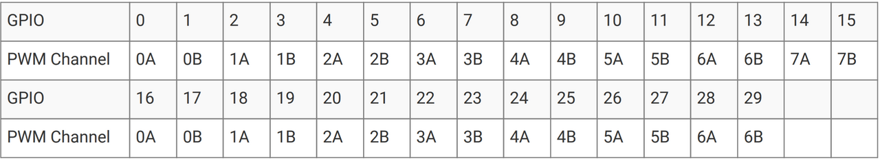
The PWM is split into 8 slices, each slice has 2 channels, and each channel can be output to 2 pins simultaneously. The B channel of each slice can be configured as an input and used as a gate or trigger for channel A. Even numbered GPIO pins are associated with Channel A and odd numbered pins are Channel B.
The To_PWM function can help you find the Slice and Channel associated with a GPIO pin.
with RP.PWM; use RP.PWM;
with RP.Clock;
with RP.GPIO;
with Pico;

procedure PWM_Demo is
    P : constant PWM_Point := To_PWM (Pico.GP0);
begin
    RP.Clock.Initialize (Pico.XOSC_Frequency);
    RP.PWM.Initialize;
    Pico.GP0.Configure (RP.GPIO.Output, RP.GPIO.Pull_Up, RP.GPIO.PWM);

    Set_Mode (P.Slice, Free_Running);
    Set_Frequency (P.Slice, 10_000_000);
    Set_Interval (P.Slice, 10_000);
    Set_Duty_Cycle (P.Slice, P.Channel, 5_000);
    Enable (P.Slice);
end PWM_Demo;
In this example, the PWM slice is configured to run at 10 MHz with an interval of 10,000. The output frequency is (Frequency / Interval). In this case, 1 KHz. The output will be high as long as the counter is less than or equal to the value passed to Set_Duty_Cycle, after which it transitions to low until the counter reaches Interval. The counter then resets to zero and begins again. In this example, the duty cycle is half of the interval, so the output has a 50% duty cycle. If the duty cycle is greater than or equal to the interval, the output is high for the entire cycle. If duty cycle is zero, the output is low for the entire cycle. Each channel’s output may be inverted using the Set_Invert procedure.
All of these parameters may be changed while the clock is running to modulate the output. See section 4.5.2.1. Pulse Width Modulation of the RP2040 datasheet for specifics about when changes to a running PWM slice take effect.
The Set_Frequency procedure attempts to calculate the correct divider value to get the desired PWM frequency. This is not always possible as the PWM divider has a fixed resolution. For accurate PWM frequency setting, use the Set_Divider procedure in combination with RP.Clock.Frequency (RP.Clock.SYS) instead, which uses the Divider fixed point type defined with the same resolution and range as the hardware divider. This allows you to calculate the error from the target frequency. Note that this is just the input frequency to the PWM, which will be divided further by the value set by Set_Interval.
Input_Clock      : constant Hertz := RP.Clock.Frequency (RP.Clock.SYS);
Target_Frequency : constant Hertz := 1_000_000;
Target_Divider   : constant Float := Float (Input_Clock) / Float (Target_Frequency);
Actual_Divider   : constant RP.PWM.Divider := RP.PWM.Divider (Target_Divider);
Divider_Error    : constant Float := Target_Divider - Float (Actual_Divider);
Actual_Frequency : constant Float := Float (Input_Clock) / Float (Actual_Divider);
Frequency_Error  : constant Float := Float (Target_Frequency) - Actual_Frequency;
Analog to Digital Converter (ADC)
The ADC is multiplexed across five channels, one of which is reserved for the internal temperature sensor. The ADC generates 12-bit samples (8.5 ENOB) at up to 500,000 samples per second.
Before ADC measurements can be done, the ADC clock must be enabled and a GPIO pin configured for Analog mode.
Configuring the ADC
with RP.ADC;  use RP.ADC;
with RP.Clock;
with RP.GPIO;
with Pico;

procedure ADC_Example is
    Channel : ADC_Channel := To_ADC_Channel (Pico.GP26);
    Value   : Analog_Value;
begin
    RP.Clock.Initialize (Pico.XOSC_Frequency);
    RP.Clock.Enable (RP.Clock.ADC);
    Pico.GP26.Configure (RP.GPIO.Analog);
    RP.ADC.Configure (Channel);

    loop
        Value := RP.ADC.Read (Channel);
    end loop;
end;
Voltage measurement
If a known reference voltage is applied to the ADC_VREF pin, the Read_Microvolts function can calculate the Microvolts integer type for you. On the Pico board, this reference is set to 3.3V unless your board has been modified. This is the default value for the VREF parameter.
declare
    use RP.ADC;
    uV : Microvolts;
begin
    uV := RP.ADC.Read_Microvolts
        (Channel => 0,
         VREF    => 3_300_000);
end;
Temperature sensor
The RP2040 has an internal temperature sensor attached to ADC channel 4. The Temperature function converts the value of this ADC channel to Celsius based on some reference values. See 4.9.5. Temperature Sensor in the RP2040 datasheet for accuracy and calibration information.
The Temperature function enables the temperature sensor for the duration of the reading and the ADC channel does not need to be configured beforehand.
declare
    C : RP.ADC.Celsius;
begin
    RP.ADC.Enable;
    C := RP.ADC.Temperature;
end;
Round robin
In round robin mode, the ADC will switch to the next enabled channel after each conversion. This allows you to sample many channels is rapid succession.
RP.ADC.Set_Round_Robin
    (Channels =>
        (0      => True,
         1      => True,
         others => False);
Sample := RP.ADC.Read;  --  Reads channel 0
Sample := RP.ADC.Read;  --  Reads channel 1
Sample := RP.ADC.Read;  --  Reads channel 0
Sample := RP.ADC.Read;  --  Reads channel 1
Continuous conversion
The ADC can be configured to continuously sample its inputs at a fixed rate. This is useful if you want to capture audio, for example. Sampling begins as soon as RP.ADC.Set_Mode is called.
declare
    use RP.ADC;
    Sample : Analog_Value;
begin
    Set_Sample_Rate (48_000);
    Set_Mode (Free_Running);
    --  DMA would be better here, see the adc_continuous example.
    loop
        Sample := RP.ADC.Read;
    end loop;
end;
Samples will be dropped if Read isn’t called fast enough. In most cases, you will want to setup a DMA channel triggered on the ADC to copy samples to a buffer while the CPU does processing. The adc_continuous example demonstrates using DMA and double buffering to capture and process two channels simultaneously.
Direct Memory Access (DMA)
The DMA peripheral can copy data from one memory location to another, freeing up the CPU to do other work while a transfer is in progress. A DMA channel is configured with a Source and Target System.Address and can be triggered by almost every other peripheral on the chip. The DMA peripheral can increment the source and/or target address after each transfer, or always use the same address.
For example, if you had a large buffer that needed to be transmitted via SPI, you could set the Source address to the beginning of the buffer and the target address to the SPI FIFO address, with the DMA channel configured to increment the source address until it reaches the end of the buffer.
with HAL.SPI;
with HAL;
with RP.DMA;  use RP.DMA;
with RP.Device;
with RP.SPI;

procedure DMA_Demo is
    Port    : RP.SPI.SPI_Port renames RP.Device.SPI_0;
    Buffer  : HAL.SPI.SPI_Data_8b (1 .. 512);
    Channel : constant RP.DMA.DMA_Channel_Id := 0;
begin
    --  Fill a buffer with sequential numbers
    for I in Buffer'Range loop
        Buffer (I) := HAL.UInt8 (I mod 255);
    end loop;
    RP.Clock.Enable (RP.Clock.PERI);
    Port.Configure (Config => (others => <>));

    RP.DMA.Enable;
    RP.DMA.Configure
        (Channel => Channel,
         Config  =>
            (Data_Size       => Transfer_8,
             Increment_Read  => True,
             Increment_Write => False,
             Trigger         => SPI0_TX,
             others          => <>));
    RP.DMA.Start
        (Channel => Channel,
         From    => Buffer'Address,
         To      => Port.FIFO_Address,
         Count   => HAL.UInt32 (Buffer'Length));

    loop
        --  Do some other work while the transfer is in progress

        if not RP.DMA.Busy (Channel) then
            --  Transfer completed, maybe begin another one.
        end if;
    end loop;
end DMA_Demo;
The DMA_Configuration record contains many other options such as reading/writing ring buffers, chaining another DMA channel after a transfer has finished, and generating checksums of data transferred through a DMA channel. See the RP2040 datasheet for more information on these options.
Programmable I/O (PIO)
The PIO peripheral consists of several state machines connected to all of the RP2040’s I/O pins. The PIO has it’s own opcodes and assembly language documented in the RP2040 datasheet. The pioasm assembler can output assembled code as a .ads file with the compiled binary represented as an array.
pioasm -p Hello -o ada src/hello.pio gen/hello.ads
The RP.PIO driver is very similar to the interface of the pico-sdk C API, as most available example code and documentation for PIO use that nomenclature. The pio_blink example demonstrates loading an assembled PIO program and executing it.
A more involved example is the RP.PIO.Audio_I2S driver, which uses PIO to generate an I2S audio stream for use with the Pimoroni Audio Pack example. The PIO program in this example was copied from the raspberrypi/pico-extras repository and it’s C startup code ported to Ada.
Interpolator
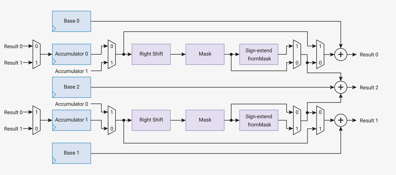
The Interpolator is capable of performing an Add, Right Shift, Mask, and Sign Extend all within a single CPU cycle, with feedback from previous cycles into the input. The datasheet indicates that this is useful for pixel blending and certain audio synthesis operations.
The RP.Interpolator package directly exposes the registers of the Interpolator peripheral. We don’t have an example for this yet because we don’t entirely understand it. You could write one!
ROM functions
The RP2040’s ROM contains a library of useful functions that can be accessed via a symbol lookup table. The RP.ROM package provides an Ada binding to this library.
Floating point library
The RP2040’s ROM includes a set of floating point functions using the CORDIC algorithm, implemented in assembly. The Cortex-M0+ has no hardware floating point unit, so if you need to do floating point math, this is as fast as it’s gonna get. These functions are connected to __aeabi symbols by RP.ROM.Floating_Point, meaning that most floating point operations are accelerated by default.
The trigonometry functions (fsin, fcos, ftan, etc) only work properly if the argument is in the range -128.0 .. 128.0, so these are not used for acceleration by default. You can call these functions directly if your application can accept these limitations. We plan to provide wrapper functions that take care of this in the near future.
A : constant Float := RP.ROM.Floating_Point.fsin (24.0);Multicore
The second CPU core in the RP2040 is put to sleep by the startup code. To wake it up and begin executing code, the RP.Multicore package provides a Launch_Core1 procedure.
See the multicore example for usage information.
Custom board support
The focus of this project is to support the RP2040 on the Raspberry Pi Pico development board, but these libraries are portable to any board that uses the RP2040 chip. We recommend creating a new yourboardname_bsp Alire crate that contains boot code, pin definitions, and peripheral drivers for your custom board’s components.
Boot code
As the RP2040 has no onboard flash, code is executed from an external flash chip. The XIP_SSI (Execute In Place Slave Serial Interface) peripheral needs to be configured for the flash chip in use. At power on, the RP2040’s ROM uses a slow 0x03 SPI flash read command to load the first 256 bytes of flash into SRAM, verify a checksum at the end of that page, then jumps to it and begins executing. This section is known as .boot2 in linker scripts. boot2 should disable the SSI, reconfigure it for the specific flash chip on the board, then re-enable it and jump to the beginning of user code, now executing from the memory mapped flash chip.
rp2040_hal includes a boot2 section written in Ada. As the compiled boot2 needs to be padded to 256 bytes with a checksum added, the rp2040_hal repository contains pre-compiled boot2 code that will be linked automatically.
Your BSP crate should set the Flash_Chip variable in alire.toml to select the correct boot2 for your board.
[configuration.values]
rp2040_hal.Flash_Chip = "w25qxx"
The following boot2 variants are supported:
generic_03
The generic_03 boot2 is compatible with any flash chip that supports the 03h read command (which is most serial NOR flash devices). The downside is that it operates in standard SPI mode so is about 3x slower than QSPI.
generic_qspi
The generic_qspi boot2 is compatible with most (but not all) QSPI NOR flash chips. It is compatible with at least the following flash chips:
-
AT25SF128A
-
GD25Q64C
-
IS25LP128F
-
W25Q16JV
-
W25Q32JV
-
W25Q64JV
-
W25Q128JV
In general, it should be compatible with any devices that meet the following requirements:
-
The "Fast Read Quad I/O" (EBh) command is supported.
-
The "Fast Read Quad I/O" instruction has 4 dummy cycles between the mode bits (M7-M0) and the first output data from the flash.
-
"Continuous read" mode is supported with mode bits (M7-M0) = A0h
-
The "Read JEDEC ID" (9Fh) command is supported.
-
The "Write Enable" (06h) command is supported.
-
If the JEDEC manufacturer ID = 9Dh (ISSI devices), then the "Quad Enable" (QE) flag is in bit 2 of Status Register 1 and the "Write Status Register 1" (01h) command is supported.
-
If the JEDEC manufacturer ID /= 9Dh, then QE flag is in bit 6 of Status Register 2 and the "Write Status Register 2" (31h) instruction is supported.
Note that this version is NOT compatible with older Winbond devices, such as the W2580DV. Those devices MUST use the w25qxx variant of boot2.
w25qxx
The w25qxx boot2 is compatible with Winbond devices that have the QE flag in bit 6 of Status Register 2, and support writing to it via a "continuous write" from Status Register 1. It is compatible with at least the following Winbond devices:
-
W2580DV
-
W25Q16JV
-
W25Q32JV
-
W25Q64JV
-
W25Q128JV
Linker script
Some startup code and a linker script are needed to generate an executable binary for the RP2040. If you are using a ZFP runtime, rp2040_hal provides reasonable defaults in the ld and startup directories. If you wish to customize these, copy both directories to your BSP crate and add the following to your alire.toml.
[configuration.values]
rp2040_hal.Use_Startup = false
Pin definitions
It is unlikely that your custom board has the same pinout as the Pico. Most BSP crates will include a package that defines symbolic names for GPIO pins that match a schematic net name or silkscreen that a user of your board would recognize.
The Adafruit Feather RP2040 example provides pin definitions for a custom board.
XOSC startup delay
Some boards, like the Adafruit Feather RP2040, have higher capacitance on the crystal oscillator traces and need to set a longer XOSC_Startup_Delay to compensate.
RP.Clock.Initialize
    (XOSC_Frequency     => 12_000_000,
     XOSC_Startup_Delay => 768_000);
--  roughly 64ms ((1.0 / 12_000_000.0) * 768_000.0)
Optimization
Binary size
The RP2040’s XIP cache is only 16 KB and reads from flash ROM are fairly slow compared to CPU cycle time and memory access. The RP.Flash.Cache.Disable procedure can be used to temporarily disable the cache and measure its performance impact on your program.
The RP.Device package instantiates every driver and device on the chip during elaboration. This has the side effect of forcing the linker to include the code for every driver’s elaboration in your binary, even if they’re not used. This adds nearly 25 KB of code for things like the USB and PIO drivers, even if you aren’t using those features. If you want to reduce binary size, you can copy only the peripherals you actually use from RP.Device into your own project.
Switches
While compile-time optimizations are no substitute for efficient algorithms, GCC can usually make your code fast and small enough for all but the most demanding tasks. Flags can be passed to the compiler and linker in a gpr project file using the Switches option. The GNAT user guide includes a list of all available switches. The example below shows the ones I use most frequently.
   package Compiler is
       for Switches ("Ada") use (
           "-Os",           --  Optimize for size. Use -O2 or -O3 for performance optimization
           "-g",            --  Generate debug symbols
           "-gnatwa",       --  All warnings
           "-gnatwl",       --  Elaboration warnings
           "-gnatVa",       --  Validity checks. Execution faster without these, but
                            --  constraints are a good idea.
           "-gnatyg",       --  Style checks. Not required, but recommended.
           "-gnatyM120",    --  Line length. Controversial.
           "-gnatyO",       --  Overriding subprograms must be explicitly marked
           "-gnata",        --  Enable assertions. Pre and Post conditions are enforced.
           "-gnatn",        --  Enable inlining. Procedures also need to be marked "with Inline" and
                            --  compiled with -O2 to actually be inlined
           "-gnatQ",        --  Keep going after errors
           "-gnatw.X",      --  Hide No_Exception_Propagation warnings.
                            --  Exceptions in ZFP are always crashes, we don't need to be reminded.
           "-gnatwB",       --  Hide Warn_On_Bad_Fixed_Value. Values assigned to fixed types may be
                            --  truncated to the nearest 'Small
           "-fstack-usage", --  Output stack usage information.
                            --  Generates .su files that can be used for stack analysis later.
           "-ffunction-sections", --  Every function gets it's own ELF section
           "-fdata-sections"      --  Every variable gets it's own ELF section
       );
   end Compiler;

   package Linker is
      for Default_Switches ("Ada") use
          Pico_BSP.Linker_Switches & (
              "-Wl,-gc-sections",        --  Discard unused ELF sections
              "-Wl,-print-memory-usage", --  Outputs memory and flash usage after linking
              "-Wl,-Map=main.map"        --  Generate a memory map file for later analysis
          );
   end Linker;
Runtime profiles
The Ada language standard requires compilers to support many features, not all of which are possible or desirable on constrained embedded devices. The pragma Restrictions directive can be used to prevent applications from using certain features. Profiles are pre-defined lists of Restrictions.
A Runtime is an implementation of a profile. The GNAT ARM toolchain includes several runtimes, which are maintained in the bb-runtimes repository.
Zero Footprint (ZFP)
Zero Footprint profiles minimize the amount of support code required to run Ada on bare metal. rp2040_hal targets the zfp-cortex-m0p runtime. ZFP runtimes do not support dynamic memory allocation, tasking, or exception propagation. A detailed discussion of ZFP restrictions can be found in this GNAT User’s Guide Supplement from AdaCore.
The Ravenscar profile
The Ravenscar Profile is less restrictive than ZFP, notably including support for tasking and multiprocessing.
The purpose of the Ravenscar profile is to restrict the use of many tasking facilities so that the effect of the program is predictable. The profile was defined by the International Real-Time Ada Workshops which met twice at the remote village of Ravenscar on the coast of Yorkshire in North-East England. A general description of the principles and use of the profile in high integrity systems will be found in an ISO/IEC Technical Report and so we shall not cover that material here.
It is reputed that the hotel in which the workshops were held was originally built as a retreat for King George III to keep a mistress. Another odd rumour is that he ordered all the natural trees to be removed and replaced by metallic ones whose metal leaves clattered in the wind. It also seems that Henry Bolingbroke landed at Ravenscar in July 1399 on his way to take the throne as Henry IV. Ravenscar is mentioned several times by Shakespeare in Act II of King Richard II; it is spelt Ravenspurg which is slightly confusing – maybe we need the ability to rename profile identifiers.
Rationale for Ada 2005 section 5.4
There is a port of Ravenscar for the RP2040, but it is more of a tech preview than release quality at this time. Projects can use the Ravenscar runtime by depending on the ravenscar_full_rp2040 Alire crate. This crate is not included in the Alire index as it is expected to be deprecated once RP2040 support is included in a gnat_arm_elf toolchain release.
alr with ravenscar_full_rp2040 --use=https://github.com/JeremyGrosser/ravenscar_full_rp2040The Ravenscar runtime includes it’s own startup and linker scripts for the RP2040. This conflicts with those provided by rp2040_hal, so you need to add a directive to alire.toml
[configuration.values]
rp2040_hal.Use_Startup = false
Next, modify your .gpr project file to use the Ravenscar runtime and remove any references to rp2040_hal’s Linker_Switches. Example Ravenscar project.
Once your project is configured, you should be able to make use of tasking, multiprocessing, and protected types. The Concurrency and Real-Time document provides several examples.
API reference
We have generated API documentation but in most cases it’s easier to just read the .ads files in rp2040_hal.
Community Support
Bugs and usability issues may be reported by opening a GitHub issue. For more general questions and feedback, join the community on forum.ada-lang.io.
License
All source code in rp2040_hal, pico_bsp, and pico_examples is available under the BSD-3-Clause license. Some portions (eg. SVD definitions) of these libraries are copied or generated from pico-sdk and are Copyright © Raspberry Pi (Trading) Ltd. and distributed under the same BSD-3-Clause license.
This documentation is made available under a Creative Commons Attribution-ShareAlike 4.0 International License.
Excerpts from the Raspberry Pi documentation are also licensed under a Creative Commons Attribution-ShareAlike 4.0 International License.
Authors
Jeremy Grosser <jeremy@synack.me>
Fabien Chouteau <fabien.chouteau@gmail.com>
Daniel King <damaki.gh@gmail.com>
Change log
2.7.1
March 27, 2026
Bugs Fixed
Embedded runtimes symbol conflict
Several symbols in RP.ROM.Floating_Point were also defined in
community-bb-runtimes, causing
builds depending on one of the light-rp2040, light-tasking-rp2040, or
embedded-rp2040 runtimes to fail when also depending on rp2040_hal. These
symbols have been renamed with a configurable RP_ prefix to avoid the name
collision. Users of rp2040_hal that need the ROM floating point functions must
call them directly now, or use one of the bb-runtimes.
Contributed by Daniel King
2.7.0
January 27, 2026
New Features
Add Current_Instruction_Address to RP.PIO
Returns the address of the currently executing instruction of a PIO SM.
Contributed by Maxim Reznik
Bugs Fixed
Prevent building with GNAT 15.2.1
gnat_arm_elf version 15.1 has a bug which prevents the bbqueue dependency from building, so that version is explicitly excluded from rp2040_hal dependencies. gnat_arm_elf 15.2 fixes that problem.
Contributed by Daniel King
Rename conflicting symbols for rp-runtimes RTS
When using the rp-runtimes RTS, several
of the aeabi symbols are defined in both rp2040_hal and the runtime. This
patch adds the RP_ prefix to those symbols if the Use_Startup configuration
flag is set.
Contributed by Maxim Reznik
2.6.0
October 3, 2025
New Features
Reset procedure for CPU Core 1
Applications can now reset the second CPU core with RP.Multicore.Reset_Core1.
Multicore tests
utilizing core1 launch, reset, and SIO FIFOs have been added.
Patch contributed by @RREE
2.5.0
July 28, 2025
Breaking Changes
RP.I2C_Master no longer supports 10-bit addressing
To simplify the implementation, only 7-bit I2C addresses are supported. If you need 10-bit addressing, use RP.I2C instead.
Bugs Fixed
16-bit I2C EEPROMs not readable with RP.I2C_Master
This was a timing issue after writing the memory address but before sending the bus read address. RP.I2C_Master has been completely rewritten and simplified. Many new unit tests ensure that this functionality is correct. An EEPROM is required on the I2C bus for unit tests now.
2.4.2
May 3, 2025
Bugs Fixed
RP.GPIO.Enable is now idempotent
Calling it twice won’t hurt anything
New Features
Custom PLL_SYS clock settings
You can now set VREG for high PLL frequencies. Added the new vendor approved 200 MHz PLL_SYS configuration.
2.4.1
May 3, 2025
Bugs Fixed
Reverted I2C_Master rewrite
Caused more problems than it solved.
2.4.0
October 24, 2024
Bugs Fixed
I2C restart after write
RP.I2C_Master now correctly sends repeated start when switching from write to read.
New Features
Touch sense capacitive charge mode
This is a workaround for RP2350 E9 errata
Updated HAL dependencies
All of the deps using HAL interfaces (cortex_m, atomic, hal, usb_embedded) have been bumped to 1.x.
2.3.0
June 10, 2024
New Features
Capacitive touch sensing
RP.PIO.Touch_Sense enables touch sensing on any GPIO pin.
Non-blocking PIO Put
RP.PIO.Try_Put can be used to perform non-blocking PIO operations without triggering interrupts or tying up a DMA channel.
Updated toolchain
Updated to GNAT 14
2.2.1
January 31, 2024
Bugs Fixed
Hang when calling reset_to_usb_boot
RP.Clock.Initialize would disable ROSC after switching to XOSC to save power. This would cause the bootloader to hang. ROSC is no longer disabled by Initialize.
2.2.0
January 27, 2024
Bugs Fixed
Compiler warnings
Various warnings introduced by GNAT 13 have been fixed.
Unit test dependencies
Removed explicit toolchain dep from unit tests.
RP.Flash.Unique_Id order reversed
Changed to match the ordering used by pico-sdk.
New Features
Watchdog Debug_Pause
Added a Debug_Pause option to RP.Watchdog.Configure to enable pausing the watchdog while a debugger is attached. This is necessary with the new CMSIS-DAP picoprobe firmware.
Updated toolchain
Updated to use GNAT 13.
2.1.1
August 11, 2023
Bugs Fixed
ROSC operation was unreliable
RP.Clock.Initialize would try to enable PLLs when ROSC was selected, which is not supported by the hardware. ROSC is now used directly when XOSC_Frequency = 0.
2.1.0
August 1, 2023
Bugs Fixed
Watchdog reset didn’t
The WDSEL register needs to be configured for the processor to reset after a watchdog timeout. RP.Watchdog.Configure now does that. The watchdog timeout during clock initialization is now 100ms.
RP.Timer.Clock did not increment when using CMSIS-DAP debuggers
The old picoprobe firmware didn’t assert the DBGPAUSE signal, but the new CMSIS-DAP compatible firmware does. This causes the timer to stop counting whenever a debugger is attached. This made it difficult to debug any program that used RP.Timer. The RP.Timer.Set_Debug_Pause procedure now allows RP.Timer to ignore the DBGPAUSE signal. Set_Debug_Pause (False, False) is called implicitly by RP.Timer.Interrupts.Enable so that programs using the Delay_* procedures will behave normally when debugged.
RP.DMA IRQ1 offset
The representation clauses for DMA IRQ1 registers were incorrect, directing all IRQ1 accesses to the wrong address.
Unit test coverage depended on an externally built gnatcov
Unit tests now depend on gnatcov 22.0.1 from the Alire index.
New Features
RP.PIO.FIFO_Status
You can now poll a PIO state machine’s FIFO status (FDEBUG register) with RP.PIO.FIFO_Status. This is useful for shortening PIO programs by eliminating IRQs, at the cost of having the processor poll the state machine occasionally.
2.0.1
January 19, 2023
Bugs fixed
Disabled ELF flags warnings
binutils 2.39, included with the latest gnat_arm_elf toolchains, added a new warning about ELF stack sections with the executable flag set. ELF headers are never written to the RP2040 flash and these flags are never read, so this warning is meaningless in this context. These warnings are now disabled in rp2040_hal.gpr.
Partial writes to GPIO interrupt registers
The GPIO INTS registers were not using Volatile_Full_Access, meaning that the CPU was performing an 8 or 16-bit write to these registers when a single bit was changed. RP2040’s memory mapped peripherals on the APB bus only support 32-bit writes, so these short writes were replicated to the adjacent bytes, clobbering unrelated interrupt flags. The GPIO register definitions have been changed to only use 32-bit writes.
Dependencies updated
-
atomic 0.4 → 0.5
-
gnat_arm_elf 12 → 12.2
-
aunit 22.0.0 → 23.0.0 (only used in tests)
2.0.0
August 22, 2022
New features
Preelaboration
Most of the drivers in rp2040_hal now have the with Preelaborate aspect, which ensures that no initialization code will be executed implicitly at startup.
I2C rewrite
RP.I2C has been rewritten to support both controller (master) and target (slave) operation. The new driver allows fine control over bus timing, repeated start, and error handling. RP.I2C_Master implements the HAL.I2C interface for applications that need to be portable or have less stringent timing and error handling requirements.
Recalculated PLL VCO frequencies
For some of the predefined RP.Clock.PLL_Config settings, the divider values have been recalculated to use lower VCO frequencies, which should reduce power consumption.
Busy wait
RP.Timer.Busy_Wait_Until will poll the timer until the specified deadline, without putting the device to sleep or triggering an interrupt.
Unique Id
The RP2040 has no unique id or serial number, but the external QSPI flash it boots from does. RP.Flash.Unique_Id reads a 64-bit "RUID" from the flash chip. The XIP peripheral must be disabled in order to execute this command, so RP.Flash.Unique_Id contains a critical section that disables interrupts.
RTC improvements
RTC alarms can now be Set or Disabled without blocking. This allows more flexible configuration of low power modes.
Breaking changes
GNAT 12 toolchain
The GNAT toolchain dependency has been updated to version 12. Several new compile time warnings were fixed. The zfp-cortex-m0p runtime has been renamed to light-cortex-m0p with this new toolchain, you will need to update the Runtime ("Ada") directive in your project file.
I2C device instances
RP.Device.I2C_0, and RP.Device.I2C_1 are now instances of RP.I2C.I2C_Port. RP.Device.I2CM_0 and RP.Device.I2CM_1 instantiate the RP.I2C_Master.I2C_Master_Port driver. If you’re updating an application from a previous version of rp2040_hal, you may need to switch to the I2CM definitions.
Alire 1.2 build profiles
rp2040_hal.gpr has been recreated using Alire 1.2, which now supports build profiles.
PWM count return type
RP.PWM.Count now returns a modular HAL.UInt16 value, rather than Natural, to better reflect the size and overflow behavior of the hardware counter.
Interrupt handling
There are now two implementations of RP_Interrupts, selectable with a configuration variable.
[configuration.values]
rp2040_hal.Interrupts = "hal"[configuration.values]
rp2040_hal.Interrupts = "bb_runtimes"All procedures in rp2040_hal that use interrupts have been moved to child packages (eg. RP.Timer.Delay_Until is now RP.Timer.Interrupts.Delay_Until with different implementations for each runtime.
With light runtimes, users may attach interrupts by calling RP_Interrupts.Attach_Handler or by redefining the weak isr_irqN symbols. Interrupt_Handler procedures no longer take an argument.
with RP2040_SVD.Interrupts;
with RP_Interrupts;
with RP.Device;
with RP.UART;

package Example is
    procedure Initialize;
    procedure UART_Handler;
end Example;

package body Example is
    procedure Initialize is
    begin
        RP_Interrupts.Attach_Handler
            (Handler => IRQ_Handler'Access,
             Id      => RP2040_SVD.Interrupts.UART0_Interrupt,
             Prio    => RP_Interrupts.Interrupt_Priority'Last);
        RP.Clock.Enable (RP.Clock.PERI);
        RP.Device.UART_0.Configure ((Enable_FIFOs => False, others => <>));
        RP.Device.UART_0.Enable_IRQ (RP.UART.Receive);
    end Initialize;

    procedure UART_Handler is
    begin
        --  handle an incoming UART frame
        null;
    end UART_Handler;
end Example;with Ada.Interrupts.Names;
with RP.Device;
with RP.UART;
package Example is
procedure Initialize;
procedure UART_Handler
with Attach_Handler => Ada.Interrupts.Names.UART0_Interrupt;
end Example;
package body Example is
procedure Initialize is
begin
RP.Clock.Enable (RP.Clock.PERI);
RP.Device.UART_0.Configure ((Enable_FIFOs => False, others => <>));
RP.Device.UART_0.Enable_IRQ (RP.UART.Receive);
end Initialize;
procedure UART_Handler is
begin
-- handle an incoming UART frame
null;
end UART_Handler;
end Example;Bugs fixed
Increased XOSC startup delay
The default value for the XOSC_Startup_Delay argument of RP.Clock.Initialize has been increased to approximately 64 milliseconds to increase reliability on some third party boards.
USB device reliability
A number of changes were made to fix RP.USB_Device behavior when used in an interrupt handler. Thanks to @Fabien-Chouteau for these patches.
1.6.0
June 6, 2022
New features
GPIO drive strength
RP.GPIO.Configure now takes a Drive argument to control GPIO drive strength, up to 12mA per pin. This should be used with caution as the sum of all current sourced or sinked by GPIO and QSPI pins may not exceed 50mA.
New unit tests
New unit tests were added for GPIO interrupts, DMA interrupts, and RP.Reset timeouts.
Coverage test script is more reliable
The coverage test script will now exit and report an error if any build or test step fails. Test output is printed after completion, regardless of error status.
Bugs fixed
Fixed warnings about unused units
The Alire 1.2.0 release candidate enables a few warnings that were previously ignored. These warnings were fixed by removing references to unused units.
DMA pacing timer tests were never run
The DMA pacing timer test was added to the test suite incorrectly and were never being run. This test is now enabled and needed some minor fixes to pass. No changes to the DMA driver were needed.
RP.PIO.Get would block forever
The Get procedure was incorrectly inverting the FIFO status register when polling to determine if there was data available. This caused it to block indefinitely if called while there was data in the FIFO. The FSTAT register type has been redefined to clarify the use of these registers and prevent this type of error in the future.
1.5.0
May 2, 2022
New features
Dynamic clock configuration
RP.Clock now exposes procedures for configuring the PLLs and changing the system clock source. Predefined PLL_Config constants are provided for common operating frequencies up to 250 MHz. While changing the system clock is now possible, it is not currently recommended. Several unit tests are currently failing with non-default clock configuration and reconfiguring peripherals after changing the clock frequency is expected to cause problems. We expect to fix these issues in the near future.
RTC delays
The RTC can now be used to delay until a specific time and date with RP.RTC.Delay_Until. The RTC should be configured before calling Delay_Until. The RTC is accurate to within a second and synchronization between the RTC and CPU clocks may add approximately 42 microseconds before and after the delay.
PWM DMA helper
RP.PWM.Compare_Reg_Address returns the address of the compare register. This address can be set as the destination of a DMA transfer to very quickly modulate PWM output (to generate audio, for example). The compare register is 32 bits wide, containing two 16 bit values, channel A in the low bits and channel B in the high bits. If you configure DMA for 16 bit transfers, the same value will be written to both channels simultaneously. There is no way to write one PWM channel without modifying the other with DMA.
Breaking changes
RP.SysTick has been removed
While testing new clock configurations, I discovered that the SysTick tests have been broken since commit cec9af51c9eb86b8daf7c37f79b4fb9221e1ecfe. The SysTick interrupt was not firing as expected, so the RP.SysTick.Delay_Until procedure would hang indefinitely.
The fix would be to enable the SysTick IRQ (15) in the NVIC. However, when I tried to do this, the PendSV interrupt was also triggered, which led to a crash because this interrupt is not defined. PendSV is meant to be used by an RTOS to implement context switching, so we don’t really want to provide a handler for it in the rp2040_hal library.
I’ve chosen to remove RP.SysTick from rp2040_hal, rather than fix the interrupt for the following reasons:
-
SysTick’s CVR and RELOAD registers are too small to accomodate a 1 KHz tick rate with a 250 MHz system clock, which we want to support.
-
Most ARM Cortex-M compatible RTOS libraries will configure SysTick and PendSV on their own, conflicting with rp2040_hal’s implementation.
-
SysTick doesn’t do anything that we can’t already do with RP.Timer.
RP_Interrupts implments weak handlers for all user interrupts
crt0.S defines a weak isr_irqN symbol for every user interrupt. Previously, the default handler for these interrupts would call the bkpt instruction, causing a debug break or reset if no debugger is attached.
Now, the isr_irqN symbols are defined as weak references to __gnat_irq_trap which is implemented by RP_Interrupts.Interrupt_Request_Handler. This handler does a lookup into an array of access procedure populated by calls to RP_Interrupts.Attach_Handler. If no handler is defined for an interrupt, the Program_Error exception is raised with a descriptive message. As ZFP runtimes do not allow exceptions to propagate, this will result in a reset.
If you need to define a custom interrupt handler, you can either use RP_Interrupts.Attach_Handler or export one of the isr_irqN symbols with the External_Name aspect. See the uart_interrupt example.
1.4.1
April 2, 2022
Bugs fixed
ROM weak symbols were overridden by the toolchain
The ROM __aeabi symbols were made weak in order to allow users to override them, but this caused the toolchain’s symbols to take precedence. The change to make these symbols weak has been reverted with this release.
1.4.0
April 2, 2022
New features
Multicore operation
The RP.Multicore, RP.Multicore.Spinlocks, and RP.Multicore.FIFO packages expose the second CPU core and the inter-core locking primitives. An example application uses the FIFO to signal core 1 to toggle an LED. Previously, multicore operation was only supported by the Ravenscar runtimes. These packages work with ZFP runtimes.
Note that many of the drivers in rp2040_hal are not safe for concurrent access and debugging race conditions between cores can be difficult. If you run into problems, try limiting access to a peripheral to one core at a time, or guard accesses with the spinlocks.
Thanks to @Fabien-Chouteau for contributing the multicore drivers.
UART and SPI interrupts
The RP.UART and RP.SPI drivers now have procedures for enabling and reading peripheral interrupt flags. These interrupts may trigger system-level interrupts or you might just poll the flags functions as needed. Thanks to @Fabien-Chouteau for these changes.
Flash cache control
Normally, all reads from the external QSPI flash use a read-through cache. The RP.Flash.Cache package can disable and flush the cache. Cache access and hit counters can provide information on cache performance. Disabling the cache may be useful if you need deterministic timing to do performance measurements or reduce jitter. If you plan to put the chip to sleep for a long period of time, the RP.Flash.Cache.Power_Down procedure may reduce power consumption further.
ROM initialization with Ravenscar
The rp_rom_float_initialize symbol has been renamed to __gnat_initialize_bootrom, for better compatibility with Ravenscar’s startup routines.
Bugs fixed
RP.PIO.WS2812 reset the PIO
When RP.PIO.WS2812.Initialize was called, it would reset the entire PIO peripheral, meaning this driver could not be used concurrently with other PIO programs.
RP.PIO.WS2812 RGB bit order
RGB color values were not encoded correctly when the Set_RGB procedure was used.
1.3.0
February 28, 2022
New features
DMA Setup can be performed without triggering a transfer
When chaining DMA channels, it’s often useful to set the From and To addresses of a channel without triggering it immediately. Previously, RP.DMA.Start both set these addresses and triggered a transfer. Now, RP.DMA.Setup performs this configuration and RP.DMA.Start with only a Channel argument will trigger the transfer. If From, To, and Count are passed as arguments to Start, then the old behavior is maintained.
Note that if Increment_Read or Increment_Write are True, then repeated calls to RP.DMA.Start will not reset the From and To addresses, they will continue from where the last transfer left off, unless Ring_Wrap and Ring_Size are configured for the DMA channel.
SysTick Delay_Until
The SysTick driver now has a Delay_Until procedure with functionality similar to RP.Timer.Delay_Until. All SysTick delays are tested to be accurate within +/- 1ms.
Flash programming
The RP.Flash package can erase and program the flash chip connected to the RP2040’s XIP interface, which is where code executes from. Note that Erase must be called before Program. See tests/src/flash_tests.adb for example usage.
Thanks to Fabien Chouteau for contributing this driver.
PIO instruction encoding
The RP.PIO.Encoding package contains a record with representation clause for each PIO opcode. The Encode function returns PIO_Instruction which can be used to fill a RP.PIO.Program array. See the pio_assemble example.
WS2812B and Audio_I2S drivers
A PIO program that implements the wire protocol for WS2812 RGB LEDs has been added as a child package of RP.PIO. The Audio_I2S driver was moved to rp2040_hal from pico_bsp.
Testing enhancements
New unit tests for SPI, RTC, and Flash functions were added. GNATcoverage is now supported for tests and reports 52% stmt+decision coverage for rp2040_hal.
Bugs fixed
I2C Mem_Write sent a repeated start after the address
The I2C Mem_Write procedure was sending a repeated start between the memory address and the data to be written. This caused issues for some I2C EEPROMs. Mem_Write has been changed to send the memory address and data both in one Master_Transmit call.
Thanks to Holger Rodriguez for reporting this issue.
SysTick returned incorrect values
RP.SysTick.Clock was returning the value of the CURRENT register, not the ticks counted by the 1ms interrupt handler. RP.SysTick.Clock now returns the ticks value, which is the number of milliseconds since SysTick was enabled.
RP.RTC.Get_Date was out of range
Get_Date would throw a ConstraintError if the hardware RTC year was 0.
RP.ROM.Floating_Point used V2 boot ROM
RP.ROM.Floating_Point did not check the boot ROM version before calling functions that are only available in V2. These calls have been removed.
-
int642float
-
uint642float
-
float2int64
-
float2uint64
-
float2double
boot2 license clarification
The boot2 directory contained source code that included a GPLv3 with runtime exception license in a comment header. These files were copied from a pull request to bb-runtimes that has not been merged. Daniel King (the original author of these files) gave permission to relicense as BSD-3-Clause, in line with the rest of rp2040_hal.
1.2.1
February 1, 2022
Bugs fixed
RP.ROM.Floating_Point used C_float
The use of C_float in the spec for RP.ROM.Floating_Point required quite a bit of type casting to/from Float in normal use. The public interface of RP.ROM.Floating_Point has been changed to use the Float type and conversions to/from C_float are performed in the package body.
1.2.0
February 1, 2022
New features
External clock output
The RP2040 can expose any of the internal clocks to an external pin. For example,
with RP.Clock; use RP.Clock;
with RP.GPIO;
with Pico;

procedure Main is
begin
    RP.GPIO.Configure (Pico.GP21, RP.GPIO.Pull_Up, RP.GPIO.CLOCK);
    Set_Source (GPOUT0, SYS);
    Enable (GPOUT0);
end Main;
See 1.4.3 GPIO_Functions in the RP2040 datasheet to determine the mapping between GPOUT channels and GPIO pins. I didn’t add a lookup table for this mapping to RP.Clock as that would introduce a dependency on RP.GPIO, which may be undesirable.
DMA pacing timers
The DMA peripheral has four internal timers that can be configured as a trigger source for any DMA channel. These pacing timers have a fractional divider connected to clk_sys. The trigger rate is defined as clk_sys * (X / Y). X and Y are 32 bit unsigned integers and can be configured with the new RP.DMA.Set_Pacing_Timer procedure.
ROM floating point
The RP.ROM and RP.ROM.Floating_Point packages have undergone a significant refactor that enables the use of the ROM floating point library in lieu of gcc’s soft float functions in most cases.
The RP.ROM.rom_id symbol has been removed, as it pointed to an incorrect value. RP.ROM.Header.Version and RP.ROM.Header.Magic should be used to identify the ROM instead.
src/startup/crt0.S must branch to the rp_rom_float_initialize after copying .data and .bss but before calling any other initialization. If you have copied or modified crt0.S in your project, you will need to integrate these changes.
The rom_hword_as_ptr symbol has been removed. We now use a type Short_Address to represent the ROM’s lookup table offsets and convert it to System.Address where needed. This is an implementation detail and shouldn’t affect users of this library.
Frequency counter accuracy
RP.Clock.Frequency now has two optional arguments: Rounded : Boolean and Accuracy : UInt4. The default behavior enables rounding and maximum accuracy, making the frequency counter results very stable. This replicates the behavior of pico-sdk. If rounding is disabled, then the counter results include some error, between 64 Hz and 2048 KHz, depending on the value of Accuracy. Higher values for Accuracy increase the counter sampling time.
Bugs fixed
RTC drift
The RTC’s internal divider value was off by one. The RTC should drift a lot less now.
RP.ADC.Disable did not disable clk_adc
To save power, clk_adc is now disabled whenever the ADC peripheral is disabled.
1.1.0
January 7, 2022
New features
Interrupt proxy
Interrupts are now proxied through the RP_Interrupts package, which is only included if the configuration Use_Startup = true, which is the default. This means the drivers can now be used with a Ravenscar runtime or other RTOS without clobbering the runtime’s interrupt handlers.
Build mode is now set to optimize by default
Previously, debug symbols were included in every build and optimization was disabled by default. Now that we’re calling this a stable release, debug mode on every build seems unnecessary.
Dependencies only use the major version
Up to this point, the version numbers of rp2040_hal, pico_bsp, and pico_examples were kept in sync. Now that we have a stable release, it’s not necessary to bump the BSP and examples for every release. Therefore, pico_bsp has been updated to depend on version ^1 of rp2040_hal, meaning any 1.x.x release. Similarly pico_examples depends on ^1 of pico_bsp. rp2040_hal has also been updated to depend on the major and minor versions of its dependencies, eg. gnat_arm_elf = "^11.2".
Bugs fixed
SPI Transmit returned too early
If Blocking = True, RP.SPI.Transmit should not return before the last bit is clocked out. The Transmit_Status function was only testing the FIFO status registers, but not testing the SSPSR.BSY flag, which indicates that the SPI clock is active. A new Busy state has been added to the SPI_FIFO_Status enum and the Transmit_Status and Receive_Status functions have been updated to test for it.
UART Transmit returned too early
Effectively the same bug as SPI.
1.0.0
December 26, 2021
New features
DMA IRQ management
RP.DMA can now configure interrupt masks for each DMA channel. If DMA_Configuration.Quiet = False, the interrupt will fire when a transfer is completed.
Unit tests
We’ve begun writing tests for rp2040_hal with the AUnit Testing Framework. Currently, there are tests for Clock, UART, SPI, GPIO, and DMA. These tests have already led to several bug fixes and we will continue to work toward more complete unit test coverage.
Breaking changes
None.
Bugs fixed
GPIO.Mode returned incorrect values
GPIO.Mode was returning the mode of the wrong pin.
PWM divider edge cases
The minimum and maximum PWM divider values were calculated incorrectly. The calculation and constraints on RP.PWM.Divider have been fixed.
RP.DMA.Status returned incorrect Transfers_Remaining
The DMA alias register layouts were incorrect. The only visible effect of this error was that RP.DMA.Status returned an incorrect value for Transfers_Remaining.
Some DMA triggers didn’t work
The DREQ register values did not have a representation clause specified, which caused triggers internal to the DMA peripheral (pacing timers and permanent triggers) to be nonfunctional.
0.7.0
October 26, 2021
New features
Documentation
Documentation has been written for most of the drivers and is available at pico-doc.synack.me.
USB device controller
The RP.USB_Device driver implements the USB.HAL.Device.USB_Device_Controller interface. This adds a dependency on the usb_embedded crate, which in turn depends on bbqueue-spark and atomic. This driver does not support USB host mode or double buffering.
The upstream SVD was updated to include USB_DPRAM registers, so all of the RP2040_SVD packages have been regenerated from source.
ADC round robin and free running mode
RP.ADC.Set_Round_Robin can be used to select multiple ADC channels to be read sequentially. RP.ADC.Set_Mode (Free_Running) will cause the ADC to continuously sample the selected channels. Paired with DMA, this means the ADC can run at up to 500,000 samples per second.
Ada boot2 code
Thanks to Daniel King, we have a working implementation of boot2 in Ada. boot2 has been moved from pico_bsp to rp2040_hal and the flash chip may be selected with the Flash_Chip Alire configuration variable.
PWM duty cycle may be set for one channel at a time
RP.PWM.Set_Duty_Cycle takes a Channel argument so that a single PWM channel’s duty cycle may be updated without affecting the other. If Channel is not specified, the duty cycle for both channels must be specified.
Default values for SPI and UART configuration
Default_SPI_Configuration and Default_UART_Configuration constants are available and are used if no arguments are supplied to RP.SPI.Configure or RP.UART.Configure.
SysTick improvements
RP.SysTick.Clock reports the 24-bit monotonic counter.
PIO interrupts
RP.PIO includes procedures for configuring and using interrupts from the PIO peripheral. Thanks to @Fabien-Chouteau for contributing these changes.
Breaking changes
Initialization procedures renamed
In order to make driver usage more consistent, the following procedures have been renamed:
-
RP.I2C_Master.Enable → RP.I2C_Master.Configure
-
RP.RTC.Initialize → RP.RTC.Configure
Toolchain dependency
rp2040_hal depends on the gnat_arm_elf toolchain in Alire. While the GNAT Community toolchains should continue to work, the FSF GNAT toolchain is the only one we will test going forward.
Startup code conflicts with Ravenscar runtimes
crt0.S and package Runtime have been moved from pico_bsp into rp2040_hal. If rp2040_hal is used as a dependency of a project built with one of the Ravenscar runtimes, rp2040_hal’s startup code will conflict with that provided by the runtime. The Use_Startup = false Alire configuration variable will prevent rp2040_hal from compiling and linking it’s startup code.
Bugs fixed
Oscillator startup delay for Feather boards
Some Adafruit Feather RP2040 boards have higher than expected capacitance on the XOSC traces and need a bit more time for the oscillator to stabilize. The XOSC_Startup_Delay parameter was added to RP.Clock.Initialize to allow BSPs to override the default startup delay. The default value should still be fine for most boards.
Clarify PWM frequency range
RP.PWM.Set_Frequency has a precondition that fails if a frequency that cannot be represented by the clock divider is requested.
Fixed crash when maximum PWM divider is specified
If Divider’Last was passed to RP.PWM.Set_Divider, the fixed point value would be rounded rather than truncated when calculating the integer part of the divider. This edge case has been fixed.
PIO relative JMP instruction addressing
If a PIO program is loaded at an offset other than zero, the JMP instructions need to be modified to point to the correct addresses. RP.PIO.Load does this rewriting. Thanks to @Fabien-Chouteau for this fix!
RP.Timer.Clock could get stuck in an infinite loop
Fix contributed by @Fabien-Chouteau.
0.6.0
September 12, 2021
New features
Clocks can be disabled
To save power, peripheral clocks can be disabled with RP.Clock.Disable. Some peripherals may exhibit unexpected behavior if their clocks are disabled. Use at your own risk.
RTC can be paused
The RP.RTC.Pause and RP.RTC.Resume procedures stop and start the RTC. This is useful if you want the RTC to stop ticking while a user is setting the time. Preconditions requiring the clock to be running have been removed from the RTC procedures. RP.RTC.Initialize still needs to be called at least once, but can be skipped if RP.RTC.Running returns True, implying that the RTC is already Initialized.
Continuous integration
A CircleCI project has been setup to compile rp2040_hal upon commit and email the author if the build fails. This is not meant to replace actual user testing on real hardware. This is just a quick check for broken builds.
Breaking changes
Delay_Microseconds no longer uses interrupts
RP.Timer.Delay_Microseconds polls the timer registers in a busy loop, rather than setting up an alarm interrupt. This should make shorter (< 10 microsecond) delays more accurate as interrupt latency is no longer a factor. RP.Timer.Delay_Until can still be used to perform interrupt-based delays with microsecond precision.
Bugs fixed
16-bit RP.SPI.Transmit did not respect the Blocking configuration option
Issue #3: If Blocking was set in the SPI_Configuration and the 16-bit version of the Transmit procedure was used, Transmit would return before all data was clocked out. Thanks to @hgrodriguez for discovering this
RP.PWM did not check that Initialize was called first
If RP.PWM.Initialize was not called before configuring PWM slices, the configuration would succeed but would generate no output. An Initialized variable has been added to RP.PWM along with a precondition on all procedures that modify PWM slices to ensure that Initialized is True. If you forget to call RP.PWM.Initialize, your program will crash on the first run.
RP.ADC.Temperature could return incorrect data
If RP.ADC.Configure (Temperature_Sensor) was not called before RP.ADC.Temperature, incorrect temperature readings would be returned. RP.ADC.Temperature now ensures the temperature sensor is configured on every call, eliminating the need to call Configure for the temperature sensor.
0.5.0
July 19, 2021
New features
UART enhancements
RP.UART now allows configuration of baud, word size, parity, and stop bits via the UART_Configuration record. The default values for the UART_Configuration record represent the typical 115200 8n1 setup.
The UART now has a Send_Break procedure, which holds TX in an active state (usually low) for at least two frame periods. Some protocols use the UART break condition to indicate the start of a new packet.
RP.UART.Receive now sets Status = Busy and returns immediately if a break condition is detected.
UART Transmit and Receive procedures now return as soon as all words have been delivered to the FIFO. FIFO status is exposed by the Transmit_Status and Receive_Status functions. This interface is the same as the I2C and SPI drivers.
The uart_echo example has been updated to demonstrate these new features.
RTC driver
The real time clock is now exposed by the RP.RTC package. It implements the HAL.Real_Time_Clock interface for getting and setting the date and time. An example project demonstrates use of the RTC. RTC alarm interrupts are not yet implemented.
Interpolator driver
The RP2040 has two interpolators per core embedded in the SIO peripheral. The RP.Interpolator package make their registers available. Some of the registers in this block support single-cycle operation, so it would be counter productive to wrap them up in procedures that may not be inlined by the compiler. There are examples in the datasheet for working with the interpolators, but I’m still trying to wrap my head around it, so there is no example here yet.
Breaking changes
UART.Enable is replaced with UART.Configure
To match the nomenclature of the other serial drivers (SPI, I2C), RP.UART now has a Configure procedure instead of Enable.
I2C addresses should include the R/W bit
The RP.I2C driver was expecting 7-bit I2C addresses to not include the R/W bit in the LSB. This was inconsistent with the other HAL.I2C implementations and would result in incorrect I2C addressing. Now, 7-bit I2C addresses should be represented as a UInt8 with the LSB set to 0. If this breaks your code, shift your I2C address left by one bit.
Bugs fixed
Improper use of the Pack clause
The Pack clause was used to enforce the memory layout of some records.
It is important to realize that pragma Pack must not be used to specify the exact representation of a data type, but to help the compiler to improve the efficiency of the generated code. Source
The Pack clause has been replaced with Component_Size and Size clauses where necessary. Thanks to @onox for pointing this out!
Use of access PIO_Device as a type discriminant
Projects depending on pico_bsp failed gnatprove in SPARK mode as the Pico.Audio_I2S package was using not null access PIO_Device as a discriminant. PIO_Device is now tagged and Pico.Audio_I2S uses not null access PIO_Device’Class, which is valid under SPARK. gnatprove still throws many warnings about side effects in the rp2040_hal drivers, but no fatal errors.
RP.ADC.Read_Microvolts was rounding incorrectly
Read_Microvolts was using Integer arithmetic to calculate VREF / Analog_Value’Last, which does not divide evenly for common VREF values. When that value was multiplied by an ADC reading, Read_Microvolts would return lower than expected results. Read_Microvolts now uses floating point to multiply ADC counts before converting the return value to Integer.
UART Transmit and Receive did not respect Timeout
The UART driver has been modified to use RP.Timer to implement timeouts and monitor FIFO status, similar to RP.SPI and RP.I2C.
SPI Transmit was nonblocking
The SPI Transmit procedure would return immediately after the last byte was written to the FIFO, but before the FIFO became empty. This behavior breaks some drivers that depend on all bytes being clocked out before proceeding. A configuration flag for Blocking behavior has been added and defaults to True.
0.4.0
June 11, 2021
New features
DMA driver
The RP.DMA package allows out of band copies between a source and target System.Address and may be triggered by a variety of events. The PIO and SPI drivers have been tested with DMA and have new functions that return their FIFO addresses.
I/O Schmitt triggers
RP.ROM.Floating_Point
The ROM floating point library is now exposed in the RP.ROM.Floating_Point package. GNAT will use gcc’s soft float implementation by default, but you may call the optimized versions in the ROM directly. The Ravenscar runtimes will replace the gcc functions with these ROM calls automatically.
I2C and SPI Timeouts
Previously, the I2C and SPI drivers did not use the Timeout argument. They now use RP.Timer to implement a timeout for all blocking operations and set Status to Err_Timeout if it expires before the blocking operation completes. The I2C peripheral may require a reset after a timeout as the bus may be in an unknown state.
SPI FIFO status is exposed with Transmit_Status and Receive_Status
You can use these functions to determine if the Transmit or Receive procedures would block. See the new spi_loopback example.
Breaking changes
PWM Set_Duty_Cycle and Set_Invert no longer use PWM_Point
These procedures have changed to take a PWM_Slice as the first argument to make them more consistent with the rest of the driver. These procedures now set both channels of a slice nearly simultaneously.
PWM Initialize must be called before any other PWM configuration
This procedure was added to fix the corruption bug discussed below.
SPI.Enable is replaced with SPI.Configure
The Configure procedure takes a SPI_Configuration record as an argument for easy static configuration.
Bugs fixed
PWM configuration is corrupted after power cycle
RP.PWM.Enable is called after configuring a PWM slice to enable it. This procedure was incorrectly resetting the PWM peripheral before enabling the slice. RP.PWM.Initialize now performs the reset and all peripheral resets have been moved to RP.Reset to avoid this mistake in the future.
PWM dividers can have a value of zero
The documentation is unclear on what this means, but my testing shows that it acts like a divider of 1, which outputs the clk_sys frequency.
Fast I2C writes would result in dropped bytes
The RP.I2C_Master driver has been modified to wait for the TX FIFO to be empty before writing a byte. This effectively reduces the FIFO depth to 1 byte. This is the same behavior as the upstream SDK.
Known issues
I2C clock is slower than expected
In 400 KHz (fast mode) operation, the I2C master generates SCL at approximately 380 KHz. I believe this is due to clock stretching caused by the new TX FIFO blocking behavior. The upstream SDK has the same behavior. According to the I2C specification, a fast mode clock may be up to 400 KHz, but specifies no minimum frequency. It may be possible to workaround this by using DMA to write to the I2C FIFO, but this is untested.